
Waterproof Backlit Marine Circuit Breaker Panel - 4 Switches, 108 x 110mm, 12V RWB5820
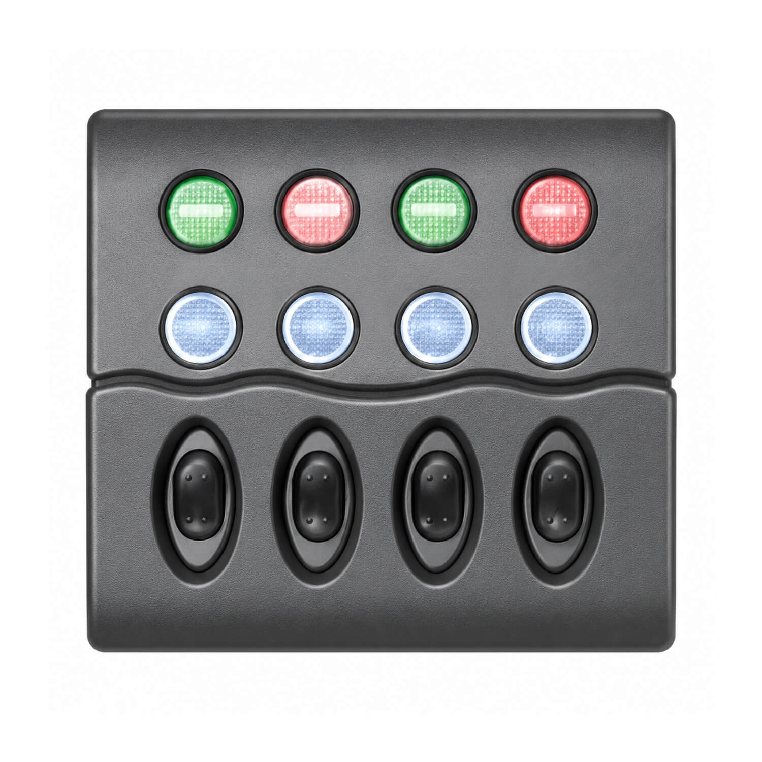

The four-switch circuit-breaker version brings resettable protection and backlit controls into a compact panel. It can be considered for a helm or auxiliary control station where the breakers need to be readily accessible. Its 110mm width and 75mm depth behind the panel should be checked against the proposed location. If a breaker operates, investigate the affected circuit before resetting it. Preserve access to the waterproof caps when arranging nearby instruments and trim.
CE-certified panel with snap-on contoured matt-black fascia, waterproof booted switches and LED backlighting. Includes mounting gasket, stainless mounting screws and 30 assorted stick-on labels. Mount horizontally or vertically. Push-to-reset circuit breakers have waterproof caps.
- Voltage: 12V only
- Switches: 4
- Size: 108 H x 110mm W
- Depth behind panel: 75mm
For layout planning, list the accessories you want to operate separately, then match each circuit to its electrical load and protection requirements. Cabin lighting, deck lighting and other auxiliary equipment are possible uses where the individual appliance requirements suit the panel. Position frequently used controls where the operator can reach them comfortably without reaching across the wheel or other instruments. Clear circuit identification also makes it easier for another person aboard to find the correct control.
Before cutting the mounting surface, check the actual panel, rear components and cable route together. Allow room to make connections without forcing wires against the panel back, and retain access for inspection and servicing. The stated face dimensions should be used for space planning; confirm the required opening from the product before cutting. Support the cable loom so movement and vibration are not carried by the terminals.
Installation should include correctly sized cable, suitable upstream protection and connections appropriate to the boat's electrical system. Have a suitably qualified installer confirm the arrangement where necessary. After installation, test each circuit individually, label it to match the connected equipment and record the layout for later fault finding.