
Heavy Duty Marine Electrical Bus Bar - 2 Stud / 20 Screw, 150A, 233 x 32mm RWB2120
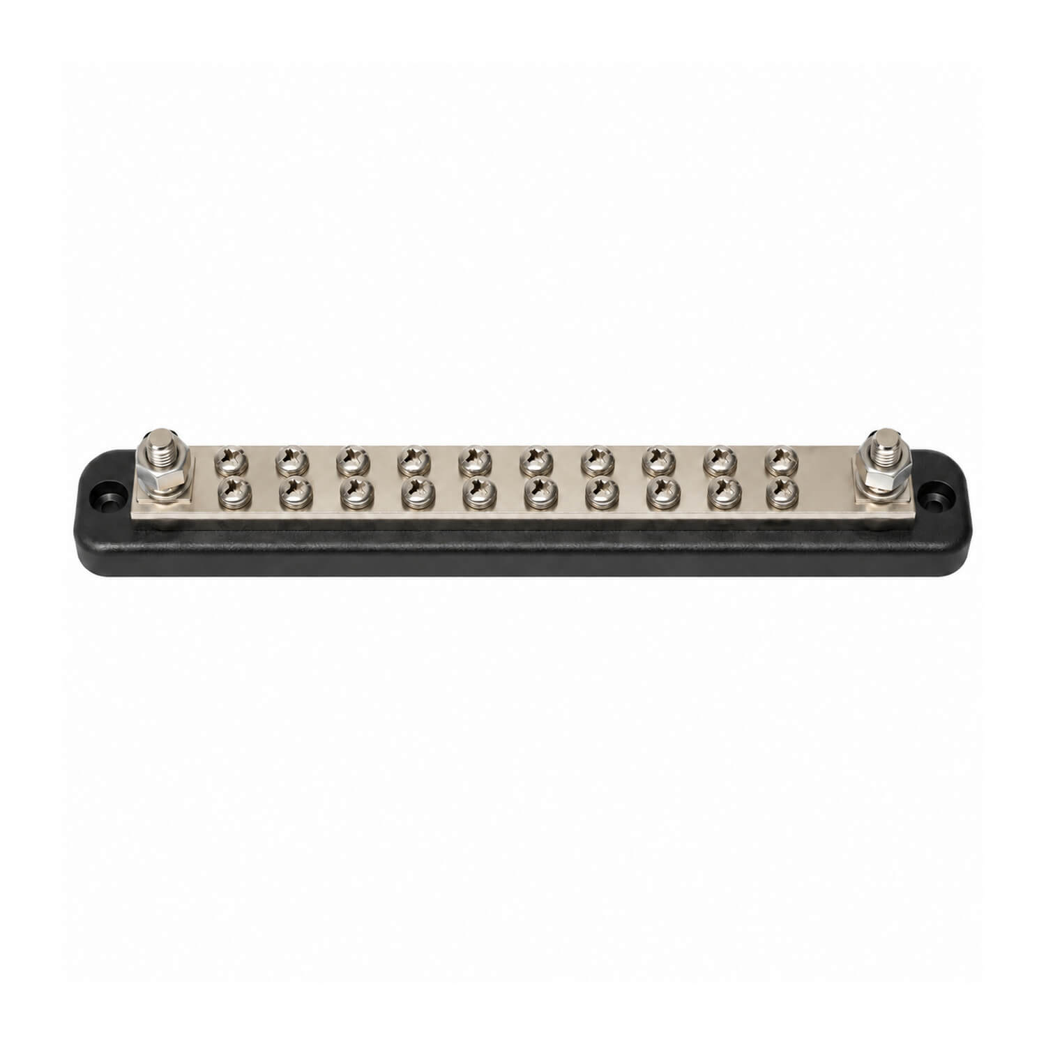

Tin-plated copper bus bar with insulated ABS base for connecting multiple DC items to one main supply.
- Fastening: two 5mm countersunk holes
- Connections: 2 studs and 20 screws
- Rating: 150A
- Size: 233 x 32mm
A bus bar provides an organised common connection point when several DC items need to connect to one main supply. Consider it when planning a distribution area or replacing a crowded collection of cable connections with a more deliberate layout. The contact arrangement should be selected to match the number and type of cable terminations in the proposed installation.
Before ordering, count the connections you need and check the terminal styles on the associated cables. Allow space around the bar for the cable lugs, bends and access to the fasteners, rather than measuring only the base footprint. Review the combined demand of the connected items against the bar's rating and the capacity of the supply cable. Each circuit's protection remains part of the wider electrical design.
For installation, choose a firm mounting surface in an accessible electrical area. Plan the cable routes before fastening the base so connections can be made without twisting or tension. Keep positive and negative arrangements clearly identified and appropriately separated within the installation. Provide suitable protection against accidental contact with live connections, following the requirements of the system being fitted.
Isolate the supply before connecting or servicing the bar. Use cable terminations matched to the actual connection hardware and secure the wiring independently of the studs or screws. Label the individual circuits so future fault-finding does not depend on tracing every cable back through the boat. During maintenance, inspect the connections for looseness, discolouration or damage and confirm that the base remains secure. Recording the connection layout is useful when accessories are added later and helps prevent the available connection points from becoming difficult to identify.
The mixed stud-and-screw layout should be checked against the actual cable terminations planned for the distribution area.