
Marine 4-Pole Battery Isolator - Continuous 240A at 12V / 120A at 24V RWB2079
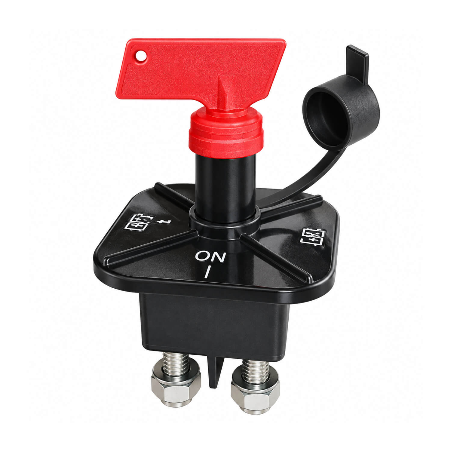

Heavy-duty isolator with rubber sealing cap and brass bolts and nuts.
- Isolates positive and negative circuits
- Removable key
- Rating at 12V: 1,200A momentary, 240A continuous
- Continuous rating at 24V: 120A
- Bolts: four 10mm brass bolts and nuts
- Voltage: 12V or 24V
A dedicated isolator provides a clear switching point for the battery circuit included in its installation. Consider it when replacing an existing switch or arranging an accessible isolation control during an electrical refit. The correct choice depends on both the physical installation and the electrical duty of the circuit being switched.
Check the system voltage and compare the relevant current ratings with the expected load. Pay attention to the difference between continuous operation and short-duration demand when assessing suitability. Measure the available mounting space and allow room for the body, cable connections and operation of the control. Select cable sizes and terminations as part of the complete circuit design, with appropriate protection elsewhere in the system.
Plan the switch position so it can be reached without moving stored gear or straining around the battery. Label what it controls and keep that information with the wiring diagram. Identify equipment that needs an ongoing supply before deciding which circuits will be isolated, so the final arrangement matches the boat's operating requirements.
Follow the engine, charging-system and battery manufacturer's guidance when operating the switch, particularly if charging equipment is running. Isolate supplies using the appropriate procedure before installation or servicing, and support heavy cables independently of the switch terminals. During maintenance, inspect the mounting, cable ends and connections for looseness or damage. Check that the operating control remains accessible after other equipment is added nearby. A clearly documented arrangement helps another operator understand the shutdown procedure and makes it easier to trace the switched circuit during later service work or fault-finding aboard.
Check the different continuous limits carefully: 240A applies at 12V, while the specified continuous limit at 24V is 120A.